Thursday, October 27, 2011

Post Three: On Car Testing

These last two weeks we continued with out on car testing. We had a set of worksheets that needed to be completed. Each worksheet had a diagnostic task that we had to perform on our cars.

Flash Codes
When ever there is a fault in a vehicle and the ECU picks it up a code is displayed. One way you can check these codes is by the way of the 'check engine' light in your dashboard flashing. It will flash a number of times indicating a code number. The check engine light can display more than one code at a time. Now how do you know what codes the check engine light is displaying? Well this is simple. There is a pattern that the check engine light flashes in. The first flashes represent the tens in the code number. There will be a very small pause and then the second flashes occur. These represent the ones in the code number. For example say the check engine light flashes three times and then pauses. After the pause it flashes six times. The flash code number being displayed here is 36. To get the flash codes to display you have to follow the correct manufacturer's procedure.

Each manufacturer has his own way of bringing the flash codes up on the display unit. We did this on my friend Richard's car. The check engine light on his car would randomly appear when he is driving and then would stay on for a length of time. It would after some time go off. This started to happen more and more rapidly while he was driving. Flash codes are done with the key ON and engine OFF position. To bring up the codes in his 1997 Mithsubishi Legnum we had to first ground the number one terminal with an earth wire on his data link connector. The Data link connector is situiated under the dash on the drivers side. It was easy to locate. After the terminal was grounded we turned on the ignition and watched the check engine lite flash. It flashed twice first and then it flashed three times. The code number it displayed was 23. There were no additional code. We searched the code number up pn the internet and found out what it meant. The code was signaling a low voltage output from the Camshaft position sensor.

After the fault code was diagnosed we did a visual inspection under the bonnet to see what was causing this problem. When we located the camshaft position sensor we noticed that there was a lot of dirt and grime that had built up around it. When we unpluged the sensor connector plug we noticed that it was dirty and was a bit clogged up with dirt and grime. This could have been causing the problem with the sensor signal being too low. So before we moved ahead we cleaned out the connecter plug and all the dirt and grime around the sensor. After the cleaning we pluged the sensor back in and checked for the flash codes again. It was still on. We had forgotten to clear the car's memory as the fault codes are recorded. To clear the code we disconnected the cars battery for 30seconds. The reason why we do it for so long is because we need to let the capacitor discharge fully. As we know a capacitor stores charge. This charge is then used to with hold information while the baterry is disconnected. After the capacitor dicharges fully the memory is lost and therefore the code is cleared off. We then connected the battery back in and checked for the codes again. There were no codes!

The cleaning of the sensor plug made a good difference in the car's behaviour. Before the car would take a few seconds to start up as it would not fire or would fire in the wrong order. This was because of the low voltage being sent to the ECU from the camshaft position sensor. The ECU at times didnt know the engine position and therefore it wouldnt fire the spark plug at the right time causing a miss fire. This was causing rough running of the engine. It would also cause the engine to miss fire every now and then. We then took the liberty of checking all the other sensors and made sure that their connection points were clean and free of dirt and grime. 


Scan Tool Diagnostics
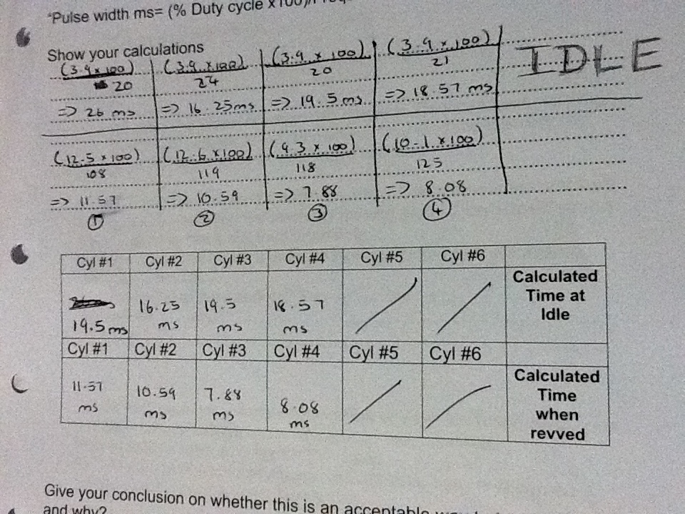
This was a fun and simple task to do. All we had to do was connect the scan tool to the vehicle and record the car's live data. The live data was recorded with the car turned on and on idle (engine running). The scan tool connects via a cable to the car's Data Link Connector. You then have to select the make and model of the car you are testing. The scan tool the brings up the data for the specified car and then shows you the car's live data. Live data shown by the scan tool is the actual real figures that the car is producing. We had to record this live data on the worksheet. 

After we had to find fault codes with this scan tool. Code number 23 came up. Camshaft position sensor voltage too low (This worksheet was done on the same day as the flash codes but was done before). We then had our lecturer create two faults under the hood. We had no idea of what he did but we had to use the scan tool and find out. So after the faults were created we checked for the codes again. Apart from the existing code (Code number 23) two other code numbers appeared. Code number 31, Map sensor voltage too high and Code number 22 ECT (engine coolant temperature) sensor voltage too high. We also observed the engine and how it was performing with the faults. The engine was stalling and didn't idle smoothly at all.

Also we recheched the car's live data to see what figures we were getting now. The intake manifold pressure had jumped up to 46 KPA from 27 KPA. The increase pressure reading would cause the ECU to supply the engine with more fuel. This is because the MAP sensor is telling the ECU that intake manifold pressure is high. The intake manifold pressure is directly related to engine load. This means that the engine now requires more fuel. But since the car is at idle the excess fuel injection causes the engine to choke resulting in the engine stalling. Another chance was in the ECT (engine coolant temperature) sensor output. It read the coolant to be at 0 degrees. This will tell the ECU that the engine is very cold. As we know when an engine is cold the ECU supplies it with more fuel bacause the fuel condenses inside the combustion chamber. So as a result even more fuel is suplied to the engine causing the engine to run very rich and therefore choking it. This resulted in a rough stalling like idle.

To locate the fault we did a visual inspection under the hood of the car. We discovered that the MAP (manifold absolute pressure) sensor and the ECT (engine coolant temperature) sensor were unpluged. Since they were unpluged the ECU got the wrong readings. To repair the fault we pluged the sensors back in and the engine began to idle normally again. We rechecked the affected readings from the live data and discovered that they were back to normal. Intake manifold pressure was back to 27 KPA and ECT sensor read 90 degrees. The next thing we had to do was to recheck the faults using the scan tool but before we did that we had to erase them from the memory. This meant that we had to disconnect the car's battery for 30seconds and then re-connect it. The two new faults were now earased and did not show up again in the scan tool. But the existing fault (code number 23) camshaft position sensor viltage too high was still there.

I found this scan tool to be a very handy tool. It has all the specs for the car you are testing which is good because it gives you something that you can compare your live data too. The live data from the vehicle makes it easier to check and see how the car is actually performing and what exactly is causing the problem.  


Fuel Pressure
This was a small and easy task to see how the fuel pressure works in cars. This test was done on a engine with a fuel pressure gauge all we had to do was run the engine in various conditions and see how the fuel pressure reacts. We did these tests when the engine was warmed up. This engine was from a Toyota Corolla; engine name 4A-FE.

The first thing we did was record the fuel pressure when the engine was idling. We had to watch the fuel pressure gauge for a few minutes till the pressure stabilized. The fuel pressure recorded was at 38 PSI. Next we had to get the maximun fuel pressure reading when the engine was at idle. To get this reading we had to use a special tool that our tutor gave us and clamp the fuel return line. Clamping the fuel return line can only be done for a very short period of time and therefore this reading had to be recorded quickly. The maximun pressure recorded when the engine is ildling was 80 PSI. We then had to record the fuel pressure at wide open throttle. Opening the throttle fully and waiting for the pressure to jump up would damage this engine so therefore we took out the vacuum line going to the fuel pressure regulator instead. This is similar to a wide open throttle senario. The pressure reading we got was 48 PSI. The last pressure reading we needed was the residual or the rest pressure. For this we had to turn the engine off and wait for a few minutes for the fuel pressure gauge to settle. The pressure reading we got was 42 PSI.

Why is it important to know a vehicle's fuel pressure?
Checking the fuel pressure of a vehicle is an important part of fuel injection system troubleshooting. Fuel pressure relates to the amount of fuel being injected into the cylinders at the injector on time. High fuel pressure will cause the engine to run rich. A car with high fuel pressure will idle rough and would idle low as the increased fuel pressure will inject too much fuel into the engine. This will cause the engine to choke, as a result it would struggle to stay on. The engine will also experience problems when cold staring as too much fuel will be injected. The car will also experience bad fuel economy. High fuel pressure can also put too much pressure on the fuel return line causing it to tear. Where as low fuel pressure will cause the engine to run lean. This will cause the engine to have lack of power as it is not getting enough fuel. It will also cause the engine to stall at lower rpm or at idle. Low fuel pressure can also cause the engine trouble when starting up. This is why it is important to know the fuel pressure in a car.


Fuel pressure is regulated in the fuel lines by the fuel pressure regulator. The fuel pressure regulator is mechanical and therefore can go faulty. A faulty fuel pressure regulator can either increase or decrease the fuel pressure permanently. This can cause damage to the fuel injection system (fuel lines) and can also cause rough engine running (bad idle and problem starting). I read this one case in which a turbo charged vehicle was modified but the fuel pressure regulator was still kept standard. When the car was driven around town normally it operated fine but as the car was taken onto the motorway the driver felt loss of power and a strong smell of fuel. When he checked under the hood of the car he noticed one of his fuel lines had a hole blown into it. Even when he got a high pressure line the same thing happened. At the end the problem turned out to be the fuel pressure regulator. Since the car was modified, when it hit boost on the highway the added boost fuel pressure was too much to handle for the standard fuel pressure regulator. So it jammed closed increasing the fuel pressure. This increased pressure became too much for the fuel lines and therefore he kept blowing holes into them.   

As you can see fuel pressure is very important to keep a track off and should always be under specification.


Exhaust Gas Analysis

This task was based around the emissions a car produces, and how they change under different circumstances. Before we began this task we needed to know what emissions are. What particles are used inside a engine and how the react in combustion. We also learnt about how a catalytic converter reduces these emissions. 


The air that we breathe consist of two major particles; Nitrogen (N2) which makes up about 78% of the air and Oxygen (O2) which makes up about 21% of the air. These particles get sucked into the engine when a engine is running. Hydrocarbons (HC) is the fuel particles. So in an intake stoke we are taking in a combination of HC + N2 + O2 in other words air and fuel. Under ideal conditions a good combustion should produce H2O (water), CO2 (carbon dioxide) and N2 (nitrogen). But this isn't always the case as the emissions produced by a car depends on many thing. For example is it running rich or running lean, is it under acceleration or is it on steady cruise. The catalytic converter helps to reduce the emissions. A catalytic converter is placed straight after the exhaust manifold. The reason for this is because it only works efficiently when it is hot. Placing the catalytic converter so close to the exhaust manifold helps it warm up fast. Inside a catalytic converter there are two seramic blocks. Each block is filled with thousands of micro pockets. There are so many of these pockets to maximise particle to metal touch. From an engine the gases you can get are Nitrogen Oxide, Hydrogencarbons and Carbon Monoxide. In the first block oxygen is seperated from the Nitrogen Oxide particle creating Oxygen and Nitrogen (the particles we have in our normal air). In the second pocket the oxygen particles are stored. The extreme heat inside the catalytic converter causes Hydrocarbon particles and the Carbon Monoxide particle to join up with the stored oxygen particles creating water and carbon dioxide.


The four particles that come out of an exhaust are:
HC : Hydrocarbons (unburnt fuel particles) 
CO : Carbon Monoxide (means you have a rich condition as there is not enough oxygen to produce CO2)
CO2 : Carbon Dioxide (this tells you the engine efficiency. Should be about 15%)
O2 : Oxygen (A lot of oxygen can indicate a lean mixture)


To perform this task we needed a car and a exhaust analyser. The car we used was a Ford Ka. Before you plug the exhaust analyser probe into the tail pipe you need to calibrate it. We first tested the normal air using the analyser probe. The readings we got was HC 12ppm, CO 0.0%, CO2 0.0% and O2 20.9%. This is a good result as it tells us that there is no CO2 and CO in the air that we are breathing. The small amount of HC was the left over HC in the probe from the last time that it was used. We then put the probe into the tail pipe and started up the car.


The first recordings from the engine were done when the car was turned on and was idling cold. The readings we got were CO 4.46%, HC 1839ppm, CO2 9.88% and O2 9.26%. This information tells us that the combustion taking place is not very efficient. As we know an engine is only efficient when it is warmed up and up to operating temperature. A cold engine also runs rich as fuel condenses. Since the car has just turned on the catalytic converter is also not working because it is still cold. This is why the emissions coming out of a cold engine are bad. We were then meant to record the exhaust gases at warm idle but unfortunatly I wasnt able to record it.


Next we ran the warm engine at 2500 RPM and recorded the four gas readings. CO 1.114%, HC 173ppm, CO2 12.7, O2 1.64%. What these readings tell us is that the engine is running rich but is still efficient. When you rev an engine you demand more power out of it. At higher revs the air content and the fuel content increases. The engine does run rich under acceleration. Because of the rich running of the engine the HC levels are relatively high. A rich mixture consist of more fuel than air as a result of this higher amounts of CO is produces as there is not a lot of O2 to make CO2. The oxygen content is also high because a rich mixture will not burn up all the intake mixture as a result higher levels of O2 is produced. The CO2 content is still good indicating a good working catalytic converter.


Now we made the engine run rich at idle. A rich running engine is not an efficient running engine. The four gas reading now were CO 1.859%, HC 197ppm, CO2 14.07%, O2 0.79%. Now as you can see the rich mixture has increased the HC and CO content. This is because the rich mixture has a higher ratio of HC (fuel) compared to O2 (air). More fuel in the combustion chamber causes for less efficient burning. This means that not all the mixture is burnt of as we have too many fuel particles. This is why the HC content and the CO content increases, because of the lack of O2 particles. The unefficient burning also has increased the O2 content slighly. The CO2 content is still within good marjin as the car has a good working catalytic  converter.


Next we made the engine run lean at idle. A lean condition is when the engine is being supplied with more air (O2) and not enough fuel (HC) to compensate for the air. The lean mixture readings were CO 0.179%, HC 959ppm, CO2 7.75%, O2 9.65%. Now as we can see the readings have changed a lot. The increase in air supply has caused the HC and O2 levels to jump really high. When the spark is created in the combustion chamber, the spark ignites the fuel particles. To create a burning the fire jumps from one fuel particle to another. Now because of the increased air supply into the engine the fuel particles are more spread out from each other. This makes it harder for the burning to jump from one fuel particle to another and as a result of this not all of the intake mixture is burnt. This is why the HC and the O2 levels have increased. The CO2 level has droped becuase of this inefficient burning taking place inside the combustion chamber.

We then disconnected a spark plug and caused one of the cylinders to not fire, creating a miss fire situation. The four gas readings were CO 0.58%, HC 1291ppm, CO2 12.40%, O2 7.61%. As above the HC and O2 content has increased. This is because on of the cylinders is not firing. This means that the intake mixture that enters that cylinder is not burnt at all and this unburnt mixture is then sent out through the exhaust valve like normal. Since none of the air and fuel is being burnt in one cylinder the HC (fuel) and O2 (air) content have increased. 


Saturday, October 1, 2011

Post Two: On car Sensors and Actuators

As per my last post we are working with sensors. Testing them and looking at how they operate. We did off car testing on sensors but this week we started on car testing for sensors.

Inputs and Outputs with a Multimeter
This week we were down in the engine room as we were working with on car sensors. The engines we worked on did not have its original ECU (but had after marker ones) and therefore the oxygen sensor and the idle air duty cycle could not be measured. We were given a chart with the sensors on one side and two columns to record the results in different engine conditions. These engines did have a plate where all the sensor signal outputs were. This made it easy for us to record the results.

The first sensor I tested was the TPS (throttle position sensor). This was the potentiometer type meter. This sensor was tested with the key ON and engine OFF position. At closed throttle the sensor measured a reading off 0.574V. This low voltage indicates to the ECU that the throttle is closed. At W.O.T (wide open throttle) the voltage reading was 3.91V. This high voltage would indicate to the ECU that the throttle is now wide open. This test also showed me then voltage scale that this sensor operates in. It operates between 0.5 to 4V. This test was done with the multimeter set into DC (direct current) volts.

The second sensor I tested was the Coolant Temperature Sensor. This sensor was also measured in DC volts. We had two readings for this sensor, Cold engine and Warmed-up engine. For cold engine the sensor gave out a voltage of 2.3V, and for warmed-up engine the sensor gave out a voltage of 0.9V. What this tells me is that the higher voltage indicates cold coolant. The ECU measures the coolant temperature to get a rough idea of how hot the engine is. So when it receives 2.3V it knows that the engine is cold and therefore will supply the engine with more fuel. Its the same when it receives a voltage of 0.9V. This will indicate to the ECU that the engine is now running at its operate temperature. Therefore no extra fuel is supplied.

The third sensor I tested was IAT (intake air temperature) sensor. I was meant to test this when the engine was cold and then hot but I didn't realize it until it was too late and the engine was warmed up. So to overcome this i placed my finger on the hot wire to increase its heat. In another was to fool it and make it read warmer air. When the air was cooler the sensor measured 3.5V. But when I placed my finger on the sensor the voltage slowly crept down to 3.3V. This showed me that the warmer the air the lower the voltage put out by the sensor. Cooler air is more dense than warmer air, and therefore it requires more fuel to burn. When the ECU sees the higher voltage it knows that cooler air is coming into the engine and therefore the engine requires more fuel to ignite efficiently. Its the opposite when the ECU gets a lower voltage, it supplies the engine with less fuel as warmer air is coming into the engine.

The forth sensor I tested was the MAP (manifold absolute pressure) sensor. This sensor was also measured in DC volts. At idle the sensor measured at 0.5V. This indicated low air pressure and high vacuum inside the intake manifold. The high vacuum was the result of the throttle valve being almost 100% closed as the car was on idle. Since the engine is still running the cylinders are still sucking in air on every intake stroke. But since we are only having a small amount of air coming into the intake manifold we create low air pressure and high vacuum. The low voltage will indicate this to the ECU and as a result of this the fuel being injected into the cylinders will decrease. I then turned off the engine to record the MAP sensor reading when the intake manifold pressure is the highest. This reading was taken in the ken ON engine OFF position. The reading was 1.83V. This voltage indicates maximum air pressure inside the manifold. Since the engine is off, the cylinders don't draw in any air. As a result of this the air pressure in side the manifold increases. But when the car is running and the MAP sensor puts out a high voltage indicating high air pressure. The ECU will increase the amount of fuel being injected into the engine.

The forth sensor I tested was the Crank/RPM sensor. This sensor was measured in two readings; Hertz (Hz) and AC (alternating current) voltage. The crank sensor measures the engine speed or a engine's RPM (revolutions per minute). I took two readings both under different engine conditions. One reading was measured at Idle rpm and the other was measured at 2500 rpm. The reading at idle rpm was 550Hz and 3.39V. The reading at 2500 rpm was 1300Hz and 6.00V. This increase in the readings shows us the increase in engine speed. The faster the engine speed the higher the readings we get. The ECU uses this information to know when to advance and retard the ignition timings. The ECU also uses this sensor to keep a track of the engine position. The engine position is used by the ECU to determine when to turn on the fuel injectors.

The fifth sensor I tested was the CAM sensor. This sensor just like the crank sensor was measured in two readings; Hertz (Hz) and AC (alternating current) voltage. The same engine condition were also used to take down the two readings. At idle rpm the reading was 23Hz and 0.9V. At 2500 rpm the reading was 60Hz and 2.05V. This increase in readings shows us an increase in engine speed. The ECU uses this sensor to tell engine position and speed. Without this sensor the ECU wont know when to spark or supple the engine with fuel. This can cause the engine to not start at all. Even if the engine does start it will run rough and will eventually stall.

The last thing I tested was the fuel injector duty cycle %. For this the multimeter was set to Duty Cycle %. All four of the fuel injectors were tested. The test was done under two different engine conditions; at idle and at acceleration. At idle the fuel injector duty cycle was 1.7%. This meant the fuel injector only injects fuel 1.7% of the time. Because the engine is at idle not a lot of fuel is required as we are not drawing a lot of air. But when we accelerated the engine the fuel injector duty cycle % increased from 1.7% to 6.5%. Since the engine was accelerating it was pulling in more air into the cylinders. More air requires more fuel to burn efficiently. Therefore the duty cycle % increased. Now the fuel injectors are held open for longer, as a result more fuel is injected into the cylinders.


Petrol Fuel Injector Testing 
This worksheet was about testing injectors on an engine to see if they are still serviceable. The first thing we had to do was to listen to each individual injector and see if they are actually working. When an injector is corking they make a sharp taping noise. This noise is very silent and cannot be heard. To listen to this noise I took a long screw driver, put it against the injector and had a listen. All the four injectors were making a taping noise; hence indicating that they are all working. The next test I had to do was to check to see if the injectors are getting enough voltage. For this test I set the multimeter on DC (direct current) voltage. The fuel injectors should be receiving battery voltage. So I recorded the battery voltage which was 14.06V. I then recorded the voltage reading of each fuel injector. All the fuel injectors had a voltage of 14.05V. This is a good result as the injectors are receiving almost full battery voltage. This means that all the circuitry for the injectors are in good condition, and are not causing any resistance. The 0.01V drop from the battery to the injector was due to the resistance of all the wires from the battery to the injectors, which is normal. This test was done with the engine in key On and engine OFF position.

(NOTE: This worksheet was performed on a different engine therefore the Duty Cycle % are different)

My next task was to record the fuel injector duty cycle % and Hertz (Hz) at idle. This was to be done for each individual injector. So i turned on the engine and let it warm up. My reason for this is that when the engine is cold it gets supplied with more fuel. This means that the fuel injector duty cycle % and Hertz readings will be higher then normal. So I let the engine warm up and then took my readings. At idle the fuel injector duty cycle % was: Injector One: 3.9%, Injector Two: 3.9%, Injector Three: 3.9%, Injector Four: 3.9%. The Hertz reading at idle was: Injector One: 20Hz, Injector Two: 24Hz, Injector Three: 20Hz, Injector Four: 22Hz. These were good results because it shows us that at idle the fuel injection is low as too much fuel is not required.

My next task was to record the fuel injector duty cycle % and Hertz (Hz) while I give the engine a short burst of acceleration (quick throttle openings). Since the engines didn't have a rev meter I wasn't too sure how much I was revving. But I tried to be consistent with my quick accelerations. My duty cycle % were Injector One: 12.5%, Injector Two: 12.6%, Injector Three: 9.3%, Injector Four: 10.1%. My Hertz readings were: Injector One: 108Hz, Injector Two: 119Hz, Injector Three:119Hz, Injector Four: 125Hz. My results do vary but that is not because the injectors were bad, it is because of human error. I was giving it the boot and it wasn't always the same. As a result of this my readings vary. These are still good results as it shows us that the fuel injectors do supply more fuel when the engine is under load.

These readings were then used to calculate the pulse width of each injector both at idle and when the engine is revved up. The pulse width is calculated in ms (Millie Seconds). The pulse width of a fuel injector is the amount of time a fuel injector is open during a cylinder's intake stroke. The formula for this is:

"Pulse width (ms) = (Duty Cycle % X 100)/Frequency (Hertz)"

My calculations are shown in the picture below but here are two examples of my calculations for injector number one at both idle and acceleration.
Idle: (3.9% X 100)/20 = 19.5ms
Acceleration: (12.5% X 100)/108 = 11.57ms


These are good results but as you can see the pulse with of the injector is lower when the engine is revved. Why is that? well it is simple when the engine is being revved the engine speed increases. Which means that each revolution now takes less time. As a result the injector open time is also reduced. But in saying that a pulse width of 11.57ms under acceleration is good and the injector is actually open for longer supping the engine with more fuel. In conclusion the injectors on this car are in good working condition. They also respond to engine conditions immediately which is another sign of good injectors.


Input Sensors and Actuators On-Vehicle
This was a similar worksheet to the one I had done before (inputs and outputs) but in this worksheet we go more in depth with our voltage readings. The first thing I had to do was to measure the voltage at each of the four injectors. For this test i set my multimeter to DC (direct current) volts. I first recorded the battery voltage which was 14.02V. The voltage measured at the fuel injectors was 14.01V. This is a good reading as all of the battery voltage is being available to the fuel injectors. Voltage plays a part in the fuel injection duration time. If the voltage was low the fuel being supplied for the engine will be low and as a result of this the engine will run lean and experience lack of power. This lack of voltage at the injector can be caused by faulty wiring (wires causing resistance to current flow), worn contact points (arching or corrosion on the points can cause resistance to current flow) and it can even be caused by bad terminal contact points at the battery (corrosion could build up between the terminal and the wire causing high resistance). This test was done in the key ON engine OFF position.

TPS
Now I had to test the voltages at the TPS (throttle position sensor). The first reading we had to do was to check the reference voltage at the TPS. My multimeter was still set to DC volts and the engine was still in the key ON engine OFF position. The reference voltage I got was 4.99V. This is a good result as we know that a potentiometer type TPS works on a scale of 0 to 5V. The reference voltage is the voltage going to the TPS. This voltage is then used up by the resistor and we get our various voltage readings. If this voltage was restricted by faulty wiring or connections, the ECU would not be able to tell the correct throttle valve angle.  
 Example: Say the TPS is only receiving a reference voltage of about 3.5V instead of 5V. This will mean that when the throttle is wide open the ECU will only get a voltage reading of 3.5V. Which will actually tell the ECU that the throttle is only opened just above half way as W.O.T requires a voltage reading of 5V. This will then result in the ECU supplying the engine with insufficient fuel. As a result the engine would run lean. We then checked the ground at the TPS. The result was 0.02V. This is a good result as it shows us that there is no restrictions to current flow on the ground side of the TPS. Restriction at the ground can also cause the car to run lean as voltage not is being used up to carry the current through the ground. Which means less voltage is available to the TPS.

My next test was to check the signal voltage coming from the TPS. This was again done in the key ON engine OFF position using DC volts. When the throttle is closed I got a signal reading of 0.5V. This is good because this low voltage indicates to the ECU that the throttle is closed. I then open the throttle about half way and got a reading of 2.3V. This was also a good result as the increase in voltage tells the ECU an increase in the throttle valve angle (more air is now going to come in). Lastly i measured the signal voltage at W.O.T, it was 4.2V. This is also a good result as it indicates to the ECU that the throttle is now wide open and that now the engine will need more fuel. Doing these reading and watching the readings on the meter rising and falling as I opened and closed the throttle indicated to me that the TPS is working fine. There were no sudden jumps or drops in the voltage being put out by the TPS. Jumps or drops in the voltage could mean resistance within the TPS.

A TPS sensor is an important sensor in a car as it tells the ECU how wide open or shut the throttle is. The TPS is mounted on the throttle body (in series with the throttle body valve). It converts the throttle valve angle into an electrical signal. This electrical signal is then sent to the ECU, indicating the throttle position. The signal sent to the ECU is in DC (direct current) volts. The ECU then uses this information to alter the air/fuel mixture. The more the throttle is opened, the more air is coming into the engine. To burn up all this air efficiently more fuel is required. This is why the ECU needs to know the throttle valve angle so that it can compensate for the air that is coming into the engine. The TPS sensor works on a 0 to 5 volt scale. When the throttle valve angel is low, say around 10 degrees. The voltage sent to the ECU is also low, say around 1.5 volts. The ECU will then look at this voltage and know that throttle is barely open and therefore it can then adjust the air/fuel mixture. The same applies when the throttle valve angle is very high, say around 75 degrees. The voltage now being sent to the ECU will also increase, say to around 4 volts. The ECU will look at this voltage and know that the throttle is now wide open and hence it will adjust its air/fuel mixture by adding more fuel.

Now how does the TPS convert the throttle valve angle into a voltage reading? Well this is very simple. Inside the TPS there are two major components; a resistor and a wiper arm. Imagine a simple series circuit with a 5 volt power supply and a resister. This is pretty much the what the TPS is. The wiper arm is in contact with this resistor at all times. Now this wiper arm is mechanically connected with the throttle valve, and as the valve moves so does the wiper arm. As the wiper arm moves on the resistor, the signal voltage output changes. At the point of contact the signal voltage that we are getting is actually the available voltage. This voltage then indicates the position of the throttle valve.


ECT (Engine Coolant Temperature) Sensor
My next sensor I tested was the engine coolant temperature sensor. The testing for this sensor was done with the multimeter set on DC (direct current) volts and with the engine running. I recorded the voltage from the sensor when the engine was cold. The reading I got was 2.9V. This is a good reading as it indicates to the ECU that the engine coolant is cold. The ECU then uses this information to get an estimate of the actual engine temperature. When the ECU sees this voltage it knows that the engine is cold and therefore supplies the engine with more fuel. The reason why it does that is because fuel needs to be in vapor form to ignite in the combustion chamber. But when the engine is cold the fuel starts to condense back into liquid form. Therefore more fuel is supplied to the engine. When the engine was warm the sensor measured at 2.0V indicating that the engine is now warm and that no extra fuel is required.

The coolant temperature sensor is basically just a thermistor. As the temperature that its measuring heats up the voltage put out by the thermistor decreases. Think of the thermistor as a voltage divider circuit, with a fixed value resistor and a variable resistor (which is the sensor). The voltage signal out is placed between the two resistors (therefore measuring available voltage). Now the voltage drop over the fixed resistor will be determined by the resistance of the variable resistor (sensor). When the temperature is cold so is the variable resistor (sensor). When the sensor is cold its resistance is very high. Now since the variable resistor has a much higher resistance then the fixed resistor, the voltage drop over the fixed resistor will be minimal. Therefore the voltage signal (available voltage) will be high. This high voltage indicates to the ECU that the thermistor is sensing cold temperatures. Now as the temperature stars to heat up, so does the temperature on the variable resistor (sensor). This increase in temperature will cause the resistance of the variable resistor to drop, causing a higher voltage drop over the fixed resistor. This higher voltage drop over the fixed resistor will cause the available voltage (voltage signal) reading to also drop. This drop in the voltage will then indicate to the ECU that the thermistor is sensing warmer temperatures.

I then tested the ground at the coolant temperature sensor. The reading i got was 0.02V. This is a good reading as it is showing us that there is no extra resistance at the ground side of the circuit. Any resistance here could cause the voltage at the sensor to drop. This would affect how the car operated when it was cold. Say the ground at the sensor was measured at 1V. That means now when the engine is cold the sensor would actually read 2V. This 2V would indicate to the ECU that the engine is warm but in fact it is cold. This will cause hesitation when the engine is trying to start up cold. It would also cause the engine to idle rough when its cold. 

MAP (Manifold Absolute Pressure) Sensor
My next sensor I tested was the MAP (manifold absolute pressure) sensor. All the readings for this sensor were taken with the multimeter set on DC (direct current) volts. The readings I took were the same readings I took for the inputs and outputs worksheet (mentioned above in the blog). When the engine is at key ON engine OFF position you get the maximum air pressure inside the intake manifold as there is no air being drawn in by the cylinders. The reading I got was 1.83V. I then turned on the engine and let it idle. At idle we have low air pressure and high vacuum. This is because the throttle valve is shut and only minimal air is allowed to come into the intake manifold. Since the engine is running the cylinders keep drawing in air, but with a lack of air supply vacuum inside the intake manifold is created. The reading I got was 0.45V. This is a good reading as the drop in voltage tells the ECU the drop of air pressure inside the intake manifold. The ECU then looks at this and alters the fuel injection levels. When you give an engine quick bursts of acceleration you create a depression inside the intake manifold as the cylinders draw in more air. This depression then causes more air to be drawn into the manifold. This increase of air causes increase of air pressure. The reading I got was 1.2V. This is a good reading as the increase in voltage tells the ECU that there is an increase in air pressure inside the intake manifold. The ECU will then use this information to alter the fuel injection levels. Basically an increase in air pressure results in more air being drawn in by the cylinders. Therefore more fuel is required by the engine to burn off all the air particles efficiently.
It is simple to explain how a MAP sensor works. Inside a MAP sensor there is a silicon chip. The silicon chip is mounted inside a reference chamber. As a result one side of this silicon chip faces the inside of the reference chamber and the other side faces the inside of the intake manifold. In side the reference chamber there is either a perfect vacuum or a calibrated pressure. This vacuum or pressure inside the reference chamber always stays the same. It never changes. The reference chamber is a fully sealed unit. As the pressure inside the intake manifold starts to change, the silicon chip starts to flex. (The silicon chip flexes with the changes in pressure of the intake manifold). As the chip start to flex the electrical resistance of the chip starts to change. This change in the chip's resistance alters the voltage output of the MAP sensor. The ECU then see's this change in the voltage output and knows that there is a change in the pressure inside the intake manifold.
Now if the reference chamber was to leak out its vacuum, the amount of resistance put out by the silicon chip would chance as the lack of vacuum inside the reference chamber would cause lack of flexing by the chip. This is not good as now the ECU will not have the correct manifold pressure readings. This will mean that it will not be able to supply the engine with the correct amount of fuel. This can result in hesitation by the engine when you accelerate and eventually cause lack of power and performance from the engine.  

IAT (Intake Air Temperature) Sensor
The last sensor I was able to test was the intake air temperature sensor. The testing for this sensor was done with the multimeter set on DC (direct current) volts and with the engine in the key ON engine OFF position. We only had to measure the voltage coming out of the sensor. Since the engine had been running before the air around the engine was warm. This meant that warm air was being sucked into the engine This caused the voltage reading from the sensor to be low. It was 2.4V. This is a good result as the lower voltage from the sensor indicates that it is picking up warm air. The IAT sensor is an important sensor because it tells the ECU how hot or how cold the intake air is. As we know colder air is more dense than warmer air this means that more fuel is required. The ECU needs to know this information to alter the air/fuel ratio depending on the air temperature. The IAT sensor is also a thermistor and how it works has been mentioned before in this blog under the ECT sensor.